| I | J | K | Output |
|---|---|---|---|
| 0 | 0 | 0 | 1 |
| 0 | 0 | 1 | 0 |
| 0 | 1 | 0 | 1 |
| 0 | 1 | 1 | 0 |
| 1 | 0 | 0 | 1 |
| 1 | 0 | 1 | 0 |
| 1 | 1 | 0 | 1 |
| 1 | 1 | 1 | 1 |
| I | J | K | Output |
|---|---|---|---|
| 0 | 0 | 0 | 1 |
| 0 | 0 | 1 | 1 |
| 0 | 1 | 0 | 1 |
| 0 | 1 | 1 | 1 |
| 1 | 0 | 0 | 1 |
| 1 | 0 | 1 | 1 |
| 1 | 1 | 0 | 1 |
| 1 | 1 | 1 | 1 |
Logic gates are among the basic building blocks of digital systems. A logic gate is a device which accepts one or more "truth-valued" inputs and produces a "truth-value" output according to a logical rule. In binary logic, the two possible "truth values" are TRUE and FALSE. Following the usual convention of Boolean algebra we'll usually associate the value 0 with TRUE and 1 with FALSE.
We'll focus our attention on logic gates in the abstract. In particular, we'll use conventional symbols for logic gates which have no connection with any specific physical implementations.
The applet below illustrates the (symbol for and) operation of an AND gate. (Remember 0=FALSE and 1=TRUE.)
(You may change the value of an input by clicking on it.)
The so-called truth table for an AND gate looks like:
| INPUT 1 | INPUT 2 | OUTPUT | |
| 0 | 0 | 0 | |
| 0 | 1 | 0 | |
| 1 | 0 | 0 | |
| 1 | 1 | 1 |
Here's an OR gate:
Q: Can you work out a truth table for an OR gate?
Q: Does the truth table for the OR gate correspond to the ordinary English usage of the word "or"?
Some more gates:
NOT
NAND
Q: What do you think the symbol for a NOR gate looks like?
Q: What do you think the truth table for a NOR gate looks like?
XOR (exclusive OR)
And now the fun part...
Complicated logical functions can be obtained by "wiring" several logic gates together. More specifically, the output of one gate may be connected to an input of another, so that the output of the first gate determines (at any given time) what truth value that input of the second gate will have. The most straightforward circuits which can be created this way are called combinational circuits.
The applet accessible through the link below allows the user to investigate simple combinational circuits that involve NOT, AND, OR, NAND, NOR and XOR gates. (XNOR is not included but may be easily simulated by attaching a NOT gate to the output of an XOR gate.) Right clicking in the background brings up a menu which includes the six types of gates listed above as choices. Selecting a gate type creates a new gate of that type on the applet canvas. The gates may be "dragged" around the canvas using the mouse. Note that a newly created gate is placed in the upper left corner of the canvas. If you create several gates in a row without moving any of them, you'll only see the first one. (The others will be hidden "underneath" the first gate.) The popup menu mentioned earlier also allows the user to add a connection. This choice brings up a dialog box which requires the user to specific the gate at whose output the new "wire" will start. The point at which the new wire will end must also be specified. This specification requires both an input line number and a gate label. Input number 1 always refers to a gate's upper input in the diagram, input 2 refers to the lower input. (The single input of a NOT gate is, of course, assigned the number 1.) Connections (or wires) in the diagram have draggable handles which give the user a little bit of control over the appearance of the schematic. (In particular, it's usually desirable to use this control to reduce or if possible eliminate wire crossings.) You should only create connections which go from left to right in the diagram. (For example, if gate A3 is further to the right on the canvas than gate O2, do not try to add a connection from the output of gate A3 to one of the inputs of gate O2.) More importantly, you should not try to connect two different outputs to the same input. (However, it is perfectly legal to connect a single output to more than one input.)
"Free" inputs default to the truth value 0, but you may toggle such a value simply by clicking on it. (An input is "free" if no output has been wired to it.) You should observe the "ripple" effect that may occur in a combinational circuit when the value of one of its inputs is altered. It is possible to use this applet to create truth tables for the outputs of a combination circuit as a function of the circuit's inputs.
Please note that this software is still in the "alpha" stage. In other words, you are here forewarned to *expect* bugs and inflexibility. For instance, you can't cancel a request to add a connection or remove a single gate from the diagram. You must name gates **precisely** when creating connections (capitalization counts). Dragging is not always smooth... especially when moving one gate across another. Etc., etc., etc. On some occassions you may need to reload the applet and simply start over. (If this applet proves to be inadequate to your digital circuit simulation needs, check out diglog from the Chipmunk toolset.) .)
Combinational circuit creater and tester
Consider the following basic properties of the logical operations AND and OR. (In the table below x, y and z represent truth values.)
| x OR y = y OR x | x AND y = y AND x | commutivity | ||
| (x OR y) OR z = x OR (y OR z) | (x AND y) AND z = x AND (y AND z) | associativity | ||
| x AND (y OR z) = (x AND y) OR (x AND z) | distributive property | |||
| x OR 0 = x | x AND 1 = x | identities |
Hopefully these properties remind you of some of the fundamental properties of ordinary addition and multiplication. Indeed, the similarities between these basic properties of logical operations and the basic properties of ordinary arithmetic inspired George Boole to create the so-called Boolean algebra. In Boolean algebra, OR is used as an additive operation and is denoted by '+', whereas AND is used as a multiplicative operation and is denoted by '·', or simple juxtaposition. With this notation, the truth tables for OR and AND may be expressed as:
|
|
The logical properties listed above are re-expressed below using Boolean notation, together with a few additional properties. (Note that a prime '′' is used to indicate logical negation [also called complementation].)
| x + y = y + x | x · y = y · x | commutivity | ||
| (x + y) + z = x + (y + z) | (x · y) · z = x · (y · z) | associativity | ||
| x + (y · z) = (x + y) · (x + z) | x · (y + z) = (x · y) + (x · z) | distributive property | ||
| x + 0 = x | x · 1 = x | identities | ||
| x + (x′) = 1 | x · (x′) = 0 | complementation | ||
| x + x = x | x · x = x | idempotency | ||
| x + 1 = 1 | x · 0 = 0 | absorption | ||
| x + x·y = x | x · (x + y) = x | absorption | ||
| (x·y)′ = x′ + y′ | (x + y)′ = x′ · y′ | DeMorgan's laws |
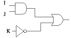
| Circuit diagram | Boolean expression | Truth table | ||||||||||||||||||||||||||||||||||||||
|---|---|---|---|---|---|---|---|---|---|---|---|---|---|---|---|---|---|---|---|---|---|---|---|---|---|---|---|---|---|---|---|---|---|---|---|---|---|---|---|---|
| I·J + K′ |
| ||||||||||||||||||||||||||||||||||||||
| ((I′+J)′ · (J·K′))′ |
|